Qucs — почти универсальный симулятор электронных цепей
Содержание:
- TINA-TI на русском
- Using manufacturers component data libraries
- Интерфейс программы Multisim
- What is Qucs-S?
- 13.3 Small signal AC two port network simulation/analysis
- 6.3 Linear and non-linear transformer models
- 7.1 Introduction
- Field Documentation
- Особенности симулятора электрических схем Qucs
- 2.2 Supported simulators
- Tinkercad для ардуино
- Usage of the whole SPICE library
- 2.4 Variable names
- 13.5 Multi-tone Large signal AC HB simulation
- CadSoft Eagle Professional v6.1.0 для Windows, Linux and Mac
- Симулятор – конструктор электронных схем “Начала электроники”
TINA-TI на русском

SPICE-симулятор для серьезных разработок, имитации работы и отладки схем для продвинутых радиолюбителей.
Программа позиционируется как SPICE-симулятор с доброжелательным и доступным интерфейсом, не требующим значительных усилий для усвоения навыков работы по проектированию и симуляции электронных устройств. Количество устройств и узлов неограниченно, подходит для масштабных проектов, фишка программы – конструирование аналоговых схем и импульсных источников питания.
В симуляторе 6 категорий устройств: базовые пассивные радиодетали, ключи, полупроводники, измерительные приборы, макромодели сложных устройств и источники. Несколько схем включены в комплект в качестве примеров.
TINA-TI предоставляет хорошие возможности симуляции и анализа. Разработки перед апробированием проверяются на ошибки (ERC) и выводится перечень найденных ошибок схемы. Ошибки выделяются маркерами.
Конструктор работает в английской и русскоязычной версиях.
Using manufacturers component data libraries
Electronic components manufacturers often provide spice models of components in
datasheets. You can attach these datasheet spice models using SPICE netlist
component. You need to perform the following steps to use Spice-model from
component datasheet. Spice netlist builder substitutes SPICE-models directly to
output netlist without any conversions.
1. Extract Spice netlist text and save it as text file. You can use any
extension for this file. Preferable are .ckt , .cir, .sp
2. Place on schematic component SPICE netlist and attach SPICE netlist nodes
to component port using standard SPICE component properties dialog.
- Simulate schematic with Ngspice/Xyce.
It’s need to note that SPICE-netlist of component must not be ended by
directive. In this case simulator exits after it reads
routine and simulation cannot be executed.
The example of spice model usage (LM358 opamp) is shown in the Figure 3.12
Figure 3.12 AC Simulation of LM358 opamp with Ngspice.
Here is the netlist of LM358 spice-model. Model can be found in LM358
datasheet.
Интерфейс программы Multisim
Начнем с изучения интерфейса программы.
Основные функциональные панели программы показаны на следующем рисунке.

Отдельный интерес представляет панель компонентов. С помощью панели компонентов осуществляется доступ к базе компонентов. При нажатии на любую из выбранных пиктограмм компонентов схем открывается окно Выбор компонента. В левой части окна осуществляется выбор необходимого компонента.

Вся база данных компонентов разделена на разделы (пассивные элементы, диоды, транзисторы, микросхемы и т. д.), а разделы на семейства (например, для диодов – это сами диоды, стабилитроны, светодиоды, тиристоры и т. д.). Надеюсь идея понятна.

Так же в окне выбора компонента можно посмотреть обозначение выбранного компонента, описание его функции, выбрать тип корпуса.
What is Qucs-S?
Qucs
-
Ngspice is recommended to use.
Ngspice is powerful mixed-level/mixed-signal circuit simulator. The
most of industrial SPICE models are compatible with Ngspice. It has an
excellent performance for time-domain simulation of switching circuits
and powerful postprocessor. -
XYCE is a new SPICE-compatible
circuit simulator written by Sandia from the scratch. It supports basic
SPICE simulation types and has an advanced RF simulation features such
as Harmonic balance simulation. -
SpiceOpus is developed by the Faculty of
Electrical Engineering of the Ljubljana University. It based on the
SPICE-3f5 code - Qucsator as backward compatible
13.3 Small signal AC two port network simulation/analysis
The spice4qucs extensions introduce post-simulation data conversion for two-port networks centred
around Qucs-S Nutmeg scripts and Qucs-S Nutmeg equation blocks. These are designed specifically to
work with Ngspice and Xyce. Conversion of two port parameters from
one format to another format is simply one example of the application of Qucs-S embedded nutmeg scripts for the
control of circuit simulation and the extraction of circuit parameters from output data.
The Xyce circuit simulator is more limited in that it does not have a post-processing scripting language
for extracting transfer function parameters and other data from simulation output. However, it
does allow SPICE style AC .PRINT statements which can include equations provided these are
written in a form constructed from the real and imaginary components of circuit voltages and
currents. In practice this is not very convenient, particularly when these equations involve many
algebraic terms. At this time the Xyce facilities for the extraction of AC data items are at a rudimentary stage in the
packages development and for this reason are not considered further in this document.
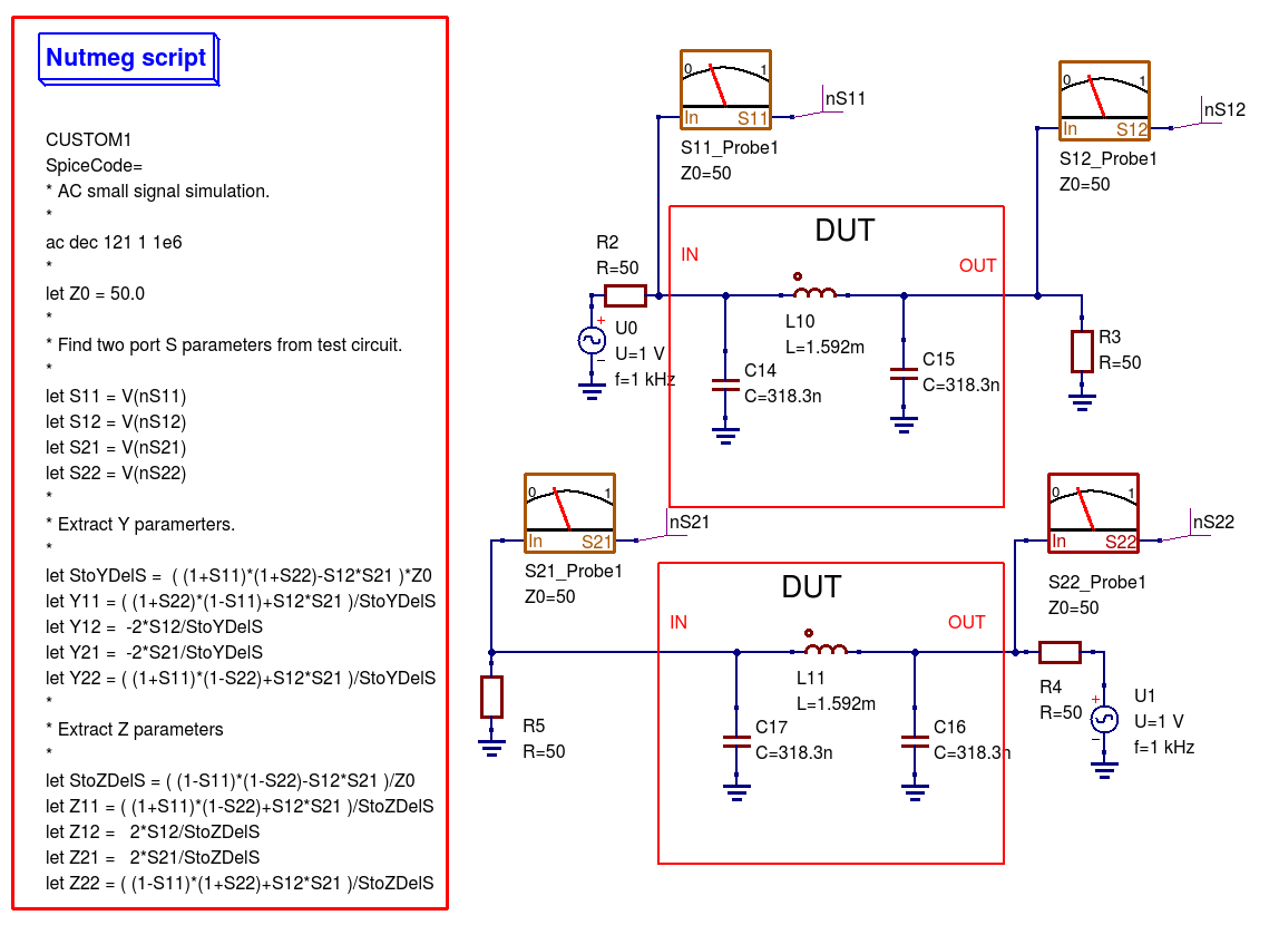
Figure 13.3 Nutmeg script controlled simulation and two-port parameter extraction.
Figure 13.3 presents an S-parameter test bench used to extract the S parameters of the same low pass filter
introduced in Figure 13.1. However, unlike Figure 13.1 Qucs/Qucs-S simulation icons are NOT attached to the
test-bench circuit schematic. Instead a Qucs-S Nutmeg script is used. This script controls the simulation sequence
and provides post processing algebraic equations which generate small signal AC \(Y\) and \(Z\) parameters from the data
output by the S-parameter probes. Figure 13.4 shows a set of simulation plots obtained with the Nutmeg script and SPICE OPUS. Identical
data was recorded with Ngspice. However, one difference was noticed when simulating circuits via the Nutmeg script route. SPICE OPUS
requires that the code words, like for example ac and let, must be entered with lower case letters, otherwise the SPICE OPUS simulation fails.
Chapter 8 presents much more detail on how to set up Nutmeg scripts and gives a number of additional examples of their use in Qucs-S circuit
simulation.
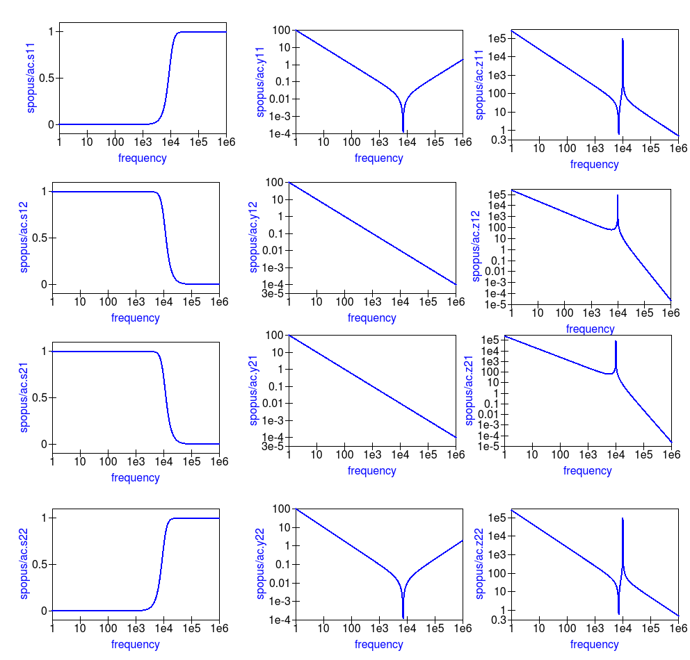
Figure 13.4 Typical S-parameter, \(Y\) parameter and \(Z\) parameter data for the test circuit given in Figure 13.3.
One of the pioneering circuit simulation features implemented by Qucs is the Equation block. This allows blocks of algebraic equations to be attached
to a circuit schematic. Any equations which do NOT include quantities computed during simulation, like circuit voltages and currents, are evaluated prior to the start of simulation.
These quantities remain fixed during simulation and may be referenced by the simulator when calculating voltages and currents. In contrast, if an Equation block includes
variables which are functions of simulation variables these are evaluated, based on the stored simulation output data, after a simulation finishes.
Qucs has a Octave style numerical analysis package built into the software for this purpose.
Qucs-S uses a slightly different approach to post simulation data processing. Both Ngspice and Xyce use an extended form of the SPICE nutmeg software for post-simulation data processing.
Unfortunately, because Xyce does not include a feature equivalent to SPICE nutmeg, AC post-simulation data processing is not possible with Xyce.
To setup and use a Qucs-S Nutmeg equation block place the Nutmeg icon on an empty schematic sheet and enter the individual variable equations in a
similar fashion to Qucs Equation blocks. Once complete copy the Nutmeg equation black to the current work circuit schematic.
Such Nutmeg equation blocks are called Templates by the Qucs-S Development Team. These templates can be saved in a project and used over and over again.
Templates add a new and important facility to Qucs-S which allows users to develop libraries of-post simulation data processing scripts and store them for future use.
See Chapters 7 and 8 for more details and examples of the use of Qucs-S Custom Simulation technology and Nutmeg equation blocks.
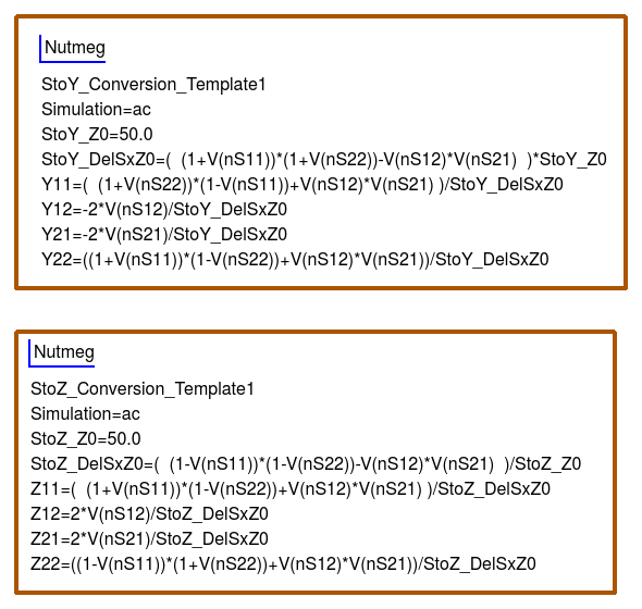
Figure 13.5 shows Qucs-S Templates for the conversion of S-parameters to \(Y\) and \(Z\) two port parameters. Note that these do NOT include commands for
simulations, for example ac ……, and do not have the same named variable defined more than ONCE.
6.3 Linear and non-linear transformer models
Qucs release 0.0.18, and earlier versions of the software, includes a number of transformer and coupled inductance models. These
models are linear with none of the important non-linear effects found in real transformers, including for example, winding resistance,
inductance fringing effects and core saturation. The transformer models introduced in this section inctroduce a number of physical effects which
correct the linear transformer limitations. The ideas introduced in their design also act as a set of
building blocks which can be used to construct more complex models. The non-linear transformer and core models can be found in the
libraries called “Transformers” and “Cores” located in the spice4qucs system library.
7.1 Introduction
For a circuit simulator to be a useful circuit design aid it must be able to simulate
a range of analogue and digital circuits which include passive components, semiconductor devices,
integrated circuits and non-electrical devices when needed. By combining Qucs with ngspice and Xyce
the number of available simulation models has increased significantly, making the spice4qucs version
of Qucs more flexible and powerful, when compared to earlier Qucs releases.
One of the primary motives behind the development of spice4qucs was to provide Qucs
users with access to published SPICE component models while keeping all the existing Qucs models and simulation
capabilities unchanged. With the first release of spice4qucs, as Qucs-0.0.19S, this aim has largely
been achieved. However, there are still significant gaps in the Qucs-0.0.19S simulation capabilities
(for example no SPICE 3f5 .PZ simulation yet) and model coverage (for example the
number of power analogue and digital models are limited). More work is planned on model development
for later releases of the software, including improvements to power device models and the introduction of
XSPICE digital models for true mixed-mode analogue-digital simulation. Any improvements and additions
to the Qucs-0.0.19S model complement will be recorded in this document as they are introduced by the
Qucs Development Team.
This chapter of the spice4qucs-help document consists of two parts; firstly a brief component specification and
a more detailed technical reference, and secondly a selection of typical simulation examples which illustrate the use of
the various component models. Part two has been added as an aid to help Qucs users appreciate
the new style software and the differences between Qucs-0.0.19S and earlier releases of Qucs.
No two circuit simulators are equipped with an identical number, and the same identical types, of circuit simulation models.
This is even true with the various implementations of SPICE developed from SPICE 3f5. Hence, by combining Qucs, ngspice and
Xyce within one
circuit simulation software package there has to be a way of identifying which models work with which simulator.
A second feature that further complicates model selection is the fact that supposedly identical models representing
the same generic device, for example a BJT, may be based on different physical device equations and a different number
of device parameters. In an attempt to identify which model works with which simulator the Qucs Development Team have
adopted the following model symbol colouring scheme; existing Qucs models are coloured dark blue (no change),
SPICE models which work with both ngspice and Xyce are coloured red, SPICE models
that only work with ngspice are coloured cyan and SPICE models that only work with Xyce are coloured dark green. This scheme
is not perfect because a number of the original Qucs models also work with ngspice and Xyce. However, for legacy reasons the
Qucs Development Team has decided not to change the colours of these models at this time. This decision will probably be
reviewed in later releases of Qucs.
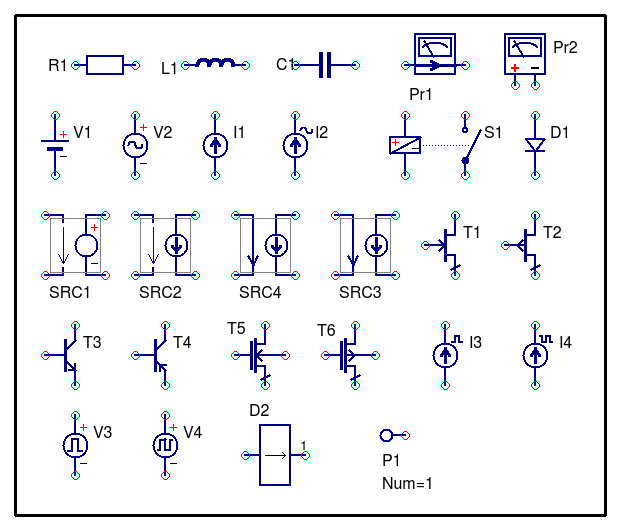
The models shown in Figure 7.1 are the original Qucs-0.18 models which can be included in ngspice and Xyce simulations. Please
NOTE that for those Qucs users who do not wish to simulate circuits with either ngspice or Xyce all the models distributed with
Qucs-0.0.18 work with Qucs-0.0.19S without any modification via the usual Simulation (key F2) command. So far no attempt
has been
made to interface Qucs Verilog-A models with ngspice or Xyce. This task is scheduled for a later spice4qucs development phase.
Field Documentation
|
private |
Definition at line of file net.h.
|
private |
Definition at line of file net.h.
|
private |
Definition at line of file net.h.
|
private |
Definition at line of file net.h.
|
private |
Definition at line of file net.h.
|
private |
Definition at line of file net.h.
|
private |
Definition at line of file net.h.
|
private |
Definition at line of file net.h.
|
private |
Definition at line of file net.h.
|
private |
Definition at line of file net.h.
|
private |
Definition at line of file net.h.
|
private |
Definition at line of file net.h.
|
private |
Definition at line of file net.h.
- net.h
- net.cpp
Особенности симулятора электрических схем Qucs
Qucs имеет графический интерфейс для ввода электрической схемы и последующей симуляции. Данные моделирования могут быть представлены в различных типах схем, в том числе Диаграмму Смита, Декартову, Табличную, Полярную, сочетание Смит-Полярной, 3D-декартову, Кривая Местоположения, Временная диаграмма и Таблица истинности.
Документация предлагает много полезных учебных руководств (WorkBook), отчетов (ReportBook) и технических описаний средств моделирования.
Другие функции включают в себя калькулятор линии электропередач, фильтр синтеза, инструмент Смит-диаграммы для питания и согласования шума, синтез аттенюатора, модель устройства и менеджер библиотек подсхемы, оптимизатор для аналоговых проектов, интерфейс Verilog-A, поддержка нескольких языков (GUI и внутренняя справочная система), подсхемы (в том числе параметры) иерархия, мощная пост-обработка данных возможно с использованием уравнения и символически определенные нелинейные и линейные устройства.
Набор инструментов
Qucs состоит из нескольких самостоятельных программ, взаимодействующих друг с другом через GUI.
GUI используется для симуляции электрической схемы, настройки моделирования, отображения результатов моделирования, написания кода VHDL и т.д.
Текстовый редактор используется, чтобы вывести на экран нетлисты и информацию о журналировании моделирования, и отредактировать файлы, включенные определенными компонентами.
Приложение синтеза фильтров может использоваться, чтобы проектировать различные типы фильтров.
Калькулятор линии передачи может использоваться, чтобы проектировать и анализировать различные типы линий передач (например, микрополосковые линии, коаксиальные кабели).
Компонент менеджер библиотеки содержит модели для реальных устройств (например, транзисторы, диоды, мосты, ОУ). Это может быть расширено пользователем.
Приложение синтеза аттенюатора может использоваться, чтобы проектировать различные типы пассивных аттенюаторов.
2.2 Supported simulators
Ngspice is a mixed-level/mixed-signal circuit simulator implemented from
three open source software packages: SPICE 3f5, Cider 1b1 and XSPICE. Ngspice is one
of the most widely used and stable current generation open source SPICE simulators available.
It implements the original SPICE3f5 simulation capabilities,
including for example, DC, AC, and transient simulation, Fourier-analysis and sensitivity analysis,
plus a significant number of extra simulation and device model extensions.
Distributed with Ngspice is a data manipulation package called Ngnutmeg. This provides
numerical analysis and visualisation routines for post processing Ngspice simulation data.
Instructions for installing Ngspice can be found on the Ngspice website at http://ngspice.sourceforge.net/download.html,
The Ngspice website also gives free access to all the distribution and development package code sources.
Xyce is an open source, SPICE-compatible, high-performance analogue circuit simulator, capable of solving extremely large circuit problems
when installed on large-scale parallel computing platforms.
It also supports serial execution on all common desktop platforms, and small-scale parallel execution on Unix-like systems.
Xyce for Linux, Microsoft Windows, and MacOS can be downloaded from the official Xyce website at https://xyce.sandia.gov/Xyce.
The Xyce parallel circuit simulator running on Linux requires installation of the openMPI libraries.
supports both Xyce-Serial and Xyce-Parallel (not currently available for the Microsoft Windows operating system).
SPICE OPUS is an improved version of SPICE based on the original SPICE 3f5 code with extensions for circuit and device performance
optimization and a transient simulation shooting method for large signal steady state AC analysis. SPICE OPUS can be downloaded from
its official website at http://www.spiceopus.si/.
Tinkercad для ардуино
Тинкеркад (Tinkercad Circuits Arduino) – бесплатный, удивительно простой и одновременно мощный эмулятор Arduino, с которого можно начинать обучение электронике и робототехнике. Он предоставляет очень удобную среду для написания своих проектов. Не нужно ничего покупать, ничего качать – все доступно онлайн. Единственное, что от вас потребуется – зарегистрироваться.
Что такое Tinkercad?

Tinkercad – это онлайн сервис, который сейчас принадлежит мастодонту мира CAD-систем – компании Autodesk. Тинкеркад уже давно известен многим как простая и бесплатная среда для обучения 3D-моделированию. С ее помощью можно достаточно легко создавать свои модели и отправлять их на 3D-печать. Единственным ограничением для русскоязычного сегмента интернета долгое время являлось отсутствие русскоязычного интерфейса, сейчас эта ситуация исправляется. Совсем недавно Тинкеркад получил возможность создания электронных схем и подключения их к симулятору виртуальной платы ардуино. Эти крайне важные и мощные инструменты способны существенно облегчить начинающим разработчикам Arduino процессы обучения, проектирования и программирования новых схем.
История создания
Tinkercad был создан в 2011 году, его авторы – Кай Бекман (Kai Backman) и Микко Мононен (Mikko Mononen). Продукт изначально позиционировался как первая Web-платформа для 3D-проектирования, в которой пользователи могли делиться друг с другом результатами. В 2013 году сервис был куплен компанией Autodesk и дополнила семейство продуктов 123D. За все это время в рамках сервиса пользователями было создано и опубликовано более 4 млн. проектов (3D-моделей).

В июне 2020 г. Autodesk решил перенести часть функционала другого своего сервиса Electroinics Lab Circuits.io, после чего Tinkercad получил крайне важные и мощные инструменты, способные существенно облегчить начинающим разработчикам Arduino процессы обучения, проектирования и программирования новых схем. Если вы уже пользовались Circuits.io, то имейте в виду, что все старые проекты Circuits.io могут быть экспортированы в Tinkercad без каких-либо проблем (о сервисе Circuits.io от Autodesk Electroinics Lab мы постараемся подробно рассказать в одной из следующих статей).
Возможности симулятора Tinkercad для разработчика Arduino
Список основного функционала и полезных фич Tinkercad Circuits:
- Онлайн платформа, для работы не нужно ничего кроме браузера и устойчивого интернета.
- Удобный графический редактор для визуального построения электронных схем.
- Предустановленный набор моделей большинства популярных электронных компонентов, отсортированный по типам компонентов.
- Симулятор электронных схем, с помощью которого можно подключить созданное виртуальное устройство к виртуальному источнику питания и проследить, как оно будет работать.
- Симуляторы датчиков и инструментов внешнего воздействия. Вы можете менять показания датчиков, следя за тем, как на них реагирует система.
- Встроенный редактор Arduino с монитором порта и возможностью пошаговой отладки.
- Готовые для развертывания проекты Arduino со схемами и кодом.
- Визуальный редактор кода Arduio.
- Возможность интеграции с остальной функциональностью Tinkercad и быстрого создания для вашего устройства корпуса и других конструктивных элементов – отрисованная модель может быть сразу же сброшена на 3D-принтер.
- Встроенные учебники и огромное сообщество с коллекцией готовых проектов.
Звучит фантастично, не правда ли? Не нужно скачивать Arduino IDE, не нужно искать и скачивать популярные библиотеки и скетчи, не нужно собирать схему и подключать плату – все, что нам нужно, находится сразу на одной странице. И, самое главное – это все действительно работает! Давайте уже перейдем от слов к делу и приступим к практическому знакомству.

Usage of the whole SPICE library
Qucs-S supports usage of the whole SPICE libraries. Such libraries will be
visible in the QucsLib tool and left-side Library dock. Library
modification will be not required, but user may need to attach components
symbols as resource files.
Let’s consider how to use it. SPICE library again will be treated as a set of
entries. You should give extension an existing SPICE
library and put in into or system Qucs library
directory (for example for Unix). Then you can
get access to this newly added SPICE library via QucsLib tool or from the
left-side dock. You will see its name and component list (Figure 3.14).
Figure 3.14 An example of a SPICE library view in the Qucs library manager.
Every found is considered as a single component. It will be shown
in the library manager and it will be available for drag’n’drop. Subcircuits
are available via an existing component.
Default symbol will be created, if there is no symbol attached to component. But
you can attach user symbol to every component. Symbol file (Qucs XML) should be
placed at the subdirectory. For example, you should create
subdirectory for file and put all necessary
symbol files int it. This location is used also for other resources such as
XSPICE CodeModel sources ( and files). Symbol file
format is considered in the previous section. Two symbol types are implemented:
1. Default symbol for all components in library. It should be placed at
file. For example will be treated as the
default symbol for library.
2. Symbol for every component ( file). For example,
will be mapped to component.
Default symbol will be substituted, if component symbol file is not found.
Please keep in mind that SPICE subcircuit names are case-insensitive, but
symbol file names may be case-sensitive for some specific platforms. In other
words may not work for component. But
will be attached properly.
You can look at SPICE library example with attached symbols here:
https://github.com/ra3xdh/qucs_spicelib Clone this repository and copy
file and subdirectory into
directory. This library contains one component (AD822 opamp).
Let’s consider library and resource files tree:
qucs_spicelib/
├── ad822
│      └── ad822.sym
└── ad822.lib
2.4 Variable names
As part of the extensions Ngspice and Xyce simulation variable names are converted from Qucs
notation to SPICE notation and vica versa. Table 2.1 shows the correspondence between the two notations.
Table 2.1 Qucs and SPICE variable equivalences
| Variable type | Qucs display notation | Spice display notation |
|---|---|---|
| DC node voltage | Node.V | V(node) |
| AC node voltage | Node.v | ac.v(node) |
| TRAN node voltage | Node.Vt | tran.v(node) |
| HB node voltage | Node.Vb | hb.v(node) |
| DC probe current | Pr1.I | i(pr1) |
| AC probe current | Pr1.i | ac.i(pr1) |
| TRAN probe current | Pr1.It | tran.i(pr1) |
Also variable prefixes used to designate data from different simulators (Table
2.2)
Table 2.2 Qucs and SPICE variable name prefixes
13.5 Multi-tone Large signal AC HB simulation
Since Xyce release 6.3 the package has supported multi-tone HB simulation. Xyce multi-tone allows more
than one tone frequency in the properties box.
Perform the following steps to setup a multi-tone Xyce HB simulation:
- Specify a list of space separated frequencies in the parameter box.
- Specify a comma separated list of the number of harmonic frequencies for each of the source signals in the parameter box.
- Construct an input signal generator using two or more series AC voltage sources, with the required frequencies and amplitudes, or
- construct an input signal generator using two or more parallel AC current sources driving a one Ohm resistor.
Normally, multi-tone HB simulation signal sources consist of two or three AC sources with different frequencies and similar amplitudes.
With two AC signal sources with nearly equal frequencies, that are not integer related, circuit modulation components can be extracted from circuit output spectra.
A multi-tone HB example illustrating this feature is given in Figure 13.8, where two AC signals of 0.8 V peak and frequencies 0.95 MHz and 1.05 MHz are applied to a simple diode circuit.
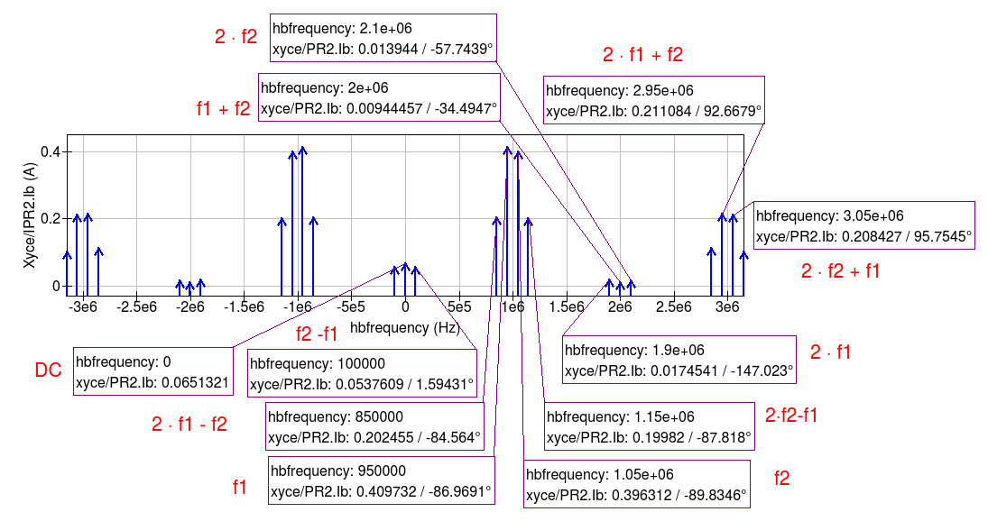
The frequencies of individual diode current spectral components are show as combinations of signal frequencies \(f_1\) and \(f_2\) and marked in red on Figure 13.9.
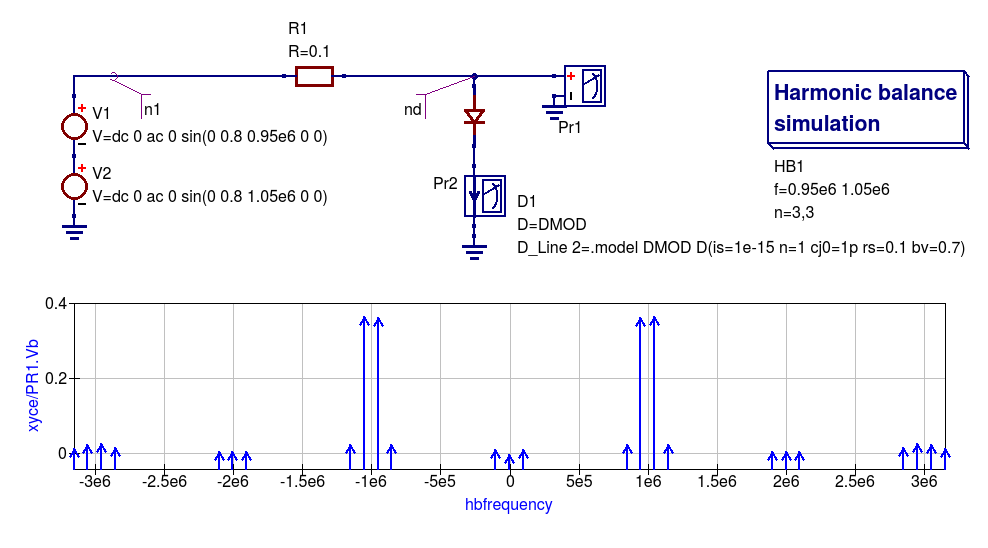
Figure 13.8 An example diode 2-tone Xyce HB simulation circuit plus diode voltage spectra.
CadSoft Eagle Professional v6.1.0 для Windows, Linux and Mac
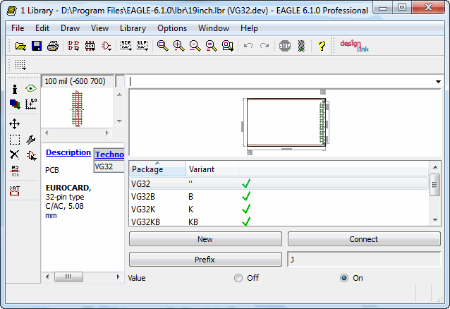
Язык интерфейса: только английский. Таблэтка: Присутствует. Программа Cadsoft EAGLE — это комплексное средство для разработки печатных плат, начиная с создания принципиальной электрической схемы и заканчивая созданием печатной платы и её трассировкой. Pro-версия позволяет разрабатывать печатные платы размером до 1600×1600 мм (16 слоёв) с разрешением до 1/10000 мм. Для этого в программе реализованы три модуля: Schematic Module, Layout Editor, Autorouter. Кроме этого программа имеет довольно большую библиотеку, содержащую множество стандартных и достаточно распространённых электрических компонентов схем, например микроконтроллеры, таким образом, не нужно будет самому рисовать изображение компонента на схеме и создавать футпринт для печатной платы. Это полноценная программа составления электрических принципиалок. Большинство компонентов схем также имеют краткое описание.
Доп. информация:
Программа включает в себя графический редактор электрических схем (Schematic Editor), редактор печатных плат (Layout Editor), весьма гибкий и удобный редактор библиотек (Library Editor) и автотрассировщик схем (Autorouter). В стандартный комплект поставки входят также модули, проверяющие правильность подключения электрических схем (ERC – Electrical Rule Check) и правильность расположения компонентов на плате (DRC – Design Rule Check). Причём две последних операции выглядят намного приятнее, чем в более продвинутых системах. EAGLE проверяет правильность дизайна и соединений схем так, что пользователь вообще не знает, что этим занимается какая-то посторонняя утилита. Это не симулятор электронных схем, который можно встретить в других софтинах. Следует отметить, что пользователю не приходится запускать для этого различные программные модули, как это сделано в P-CAD или ACCEL EDA — все переходы осуществляются внутри самой программы. Имеется также возможность заливки заданного пространства полигонами. EAGLE позволяет проектировать многослойные платы, содержащие до 16 слоёв и имеющие размеры 1626х1626 мм при разрешающей способности 0,0001 мм. Систему единиц (дюймовую или метрическую) можно изменить на любой фазе работы с проектом без каких-либо потерь.
Одним из основных достоинств данного пакета профессионалы выделяют полную синхронность изменений в проекте. К примеру, если вы изменили или удалили какой-либо компонент схемы, это тут же отразится на рисунке платы. В таких программах, как ACCEL EDA, P-CAD и OrCAD необходимо постоянно контролировать весь проект, при малейших изменениях и на любом этапе работы. Кроме того, в EAGLE откат событий (UNDO) возможен на любое количество действий (такое не позволяет делать даже самый мощный на сегодняшний день CAD – ACCEL EDA).
Симулятор – конструктор электронных схем “Начала электроники”
Существует очень интересная программа, которая представляет собой несложный симулятор для демонстрации работы электрических схем и работы измерительных приборов. Удобство его не только в наглядности, но и в том, что интерфейс на русском языке. Она позволяет смоделировать на макетнице очень простые принципиальные схемы. Называется программа “Начала электроники”. Ссылка на нее внизу страницы, видео канала Михаила Майорова.
Программа работает, начиная от Windows 98 и заканчивая Windows 7. Интерфейс выглядит следующим образом.

Внизу располагается чертеж печатной платы, но для нас наибольший интерес представляет панелька с макетной платой. Наверху кнопки управления: загрузить схему из файла, сохранить схему, очистка макетной платы, получить мультиметр, получить осциллограф, показать параметры деталей, состояние деталей, справочник, (кратко изложены понятия об электричестве), небольшой список лабораторных работ для самостоятельного их проведения, инструкция по пользованию симулятором, информация об авторах, выход из программы.
На видео о том, как работает симулятор цепи.
Что можно собрать на симуляторе схем?
На этом простом симуляторе можно собрать много интересных вещей. Для начала давайте смоделируем обычный фонарик. Для этого нам потребуется лампочка, две батарейки и, естественно, все это надо будет соединить перемычками. Ну и какой же фонарик без выключателя и лампочки?
Двойным щелчком вызываем окно параметров батарейки. На появившейся вкладке видим напряжение, внутреннее сопротивление, показывающее ее мощность, миниполярность. В данном случае батарейка вечная.
Когда схема собрана, нажимаем два раза выключатель и лампочка почему то сгорает. Почему? Суммарное напряжение последовательно соединенных батареек 3 вольта. Лампочка по умолчанию была на 2,5 вольта, поэтому и сгорела. Ставим 3-вольтовую лампочку и снова включаем. Лампочка благополучно светится.
Теперь берем вольтметр. Вот у него загораются “ладошки”. Это измерительные щупы. Давайте перенесем щупы к лампочке и поставим измерение постоянного напряжения с пределом 20 Вольт. На мониторе показывает 2,97 вольта. Теперь попробуем измерить силу тока. Для этого берем второй мультиметр. Прибор, подсоединенный в схему, показал почти 50 миллиампер.
Практически как на настоящем мультиметре, можно измерить множество параметров. Есть также в симуляторе осциллограф, у которого даже регулируется яркость луча. Кроме того, есть реостат, можно двигать движок. Есть переменный конденсатор, шунты, нагревательная печка, резисторы, предохранители и другое. К сожалению, в данном симуляторе нет транзисторов. Конструктор электрика отлично подходит для начала изучения основ электроники.
Выводы по программе “Начала электроники”
Для начинающих радиолюбителей это просто замечательная программа, простая и написанная на русском языке, на которой можно научиться многим операциям со схемами, мультиметром и осциллографом. Пригодится она и для разработки оптимальных решений для электрических плат. программу “Начала электроники”
Для продвинутых задач нужны другие программы, которые также есть в интернете. Одна из популярных – Workbench Electronic.

